© 2001 rev.2020
the Engineman's
Beneath this photo of the cylinder block from a model tugboat engine is a gallery of color photographs of various miniature engines that I have made in the early part of the past 30 years.
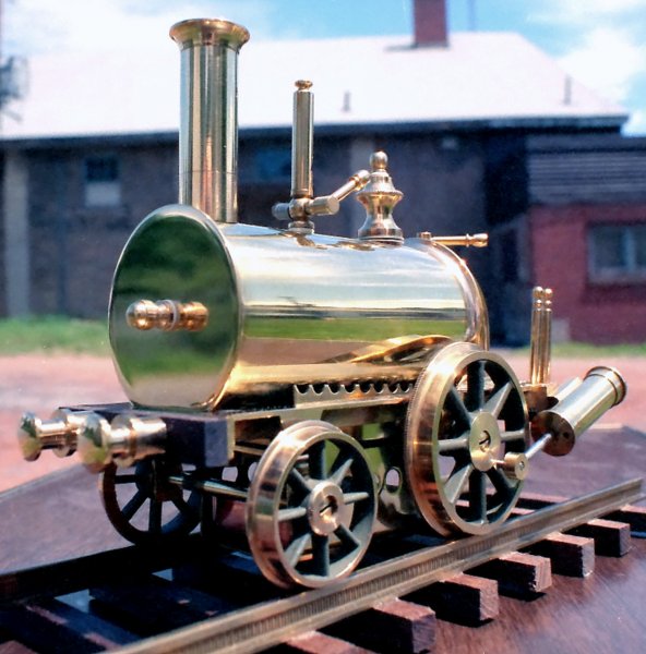
This is a Carpet Engine - a model of a model. These were the toy trains of the mid-Nineteenth century. They loosely resembled the locomotives of the day and were constructed entirely of brass. This one is called the Birmingham Dribbler. It was made from a package of castings and materials that I purchased from Maxwell Hemmens in Thorganby, England. Mr. Hemmens told me that they were dubbed "dribblers" or "piddlers" because of the wet trails left behind as they lumbered across the living room carpet under steam.
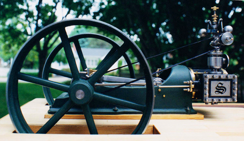
This engine was made from a set
of Stuart Turner S50 castings.
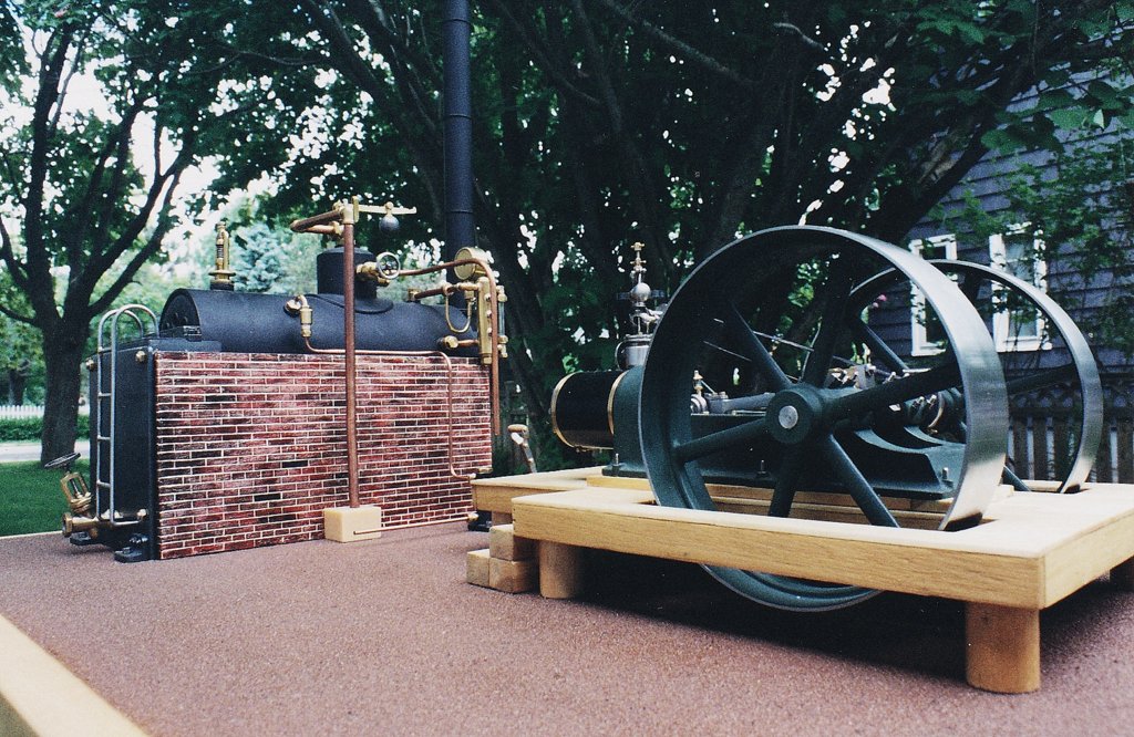
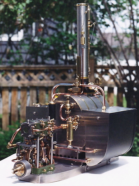
The mill engine is coupled to a Cornish boiler fashioned from silver brazed copper. It is 2 1/2 inches in diameter and the flue contains 16 Galloway tubes. The riveted exterior is only a decorative cover not attached to the pressure vessel.
There are six miniature incandescent lamps on the model, as well as a working voltmeter and pilot light. The control panel houses a voltage regulator to supply a precise 3-volt output. The plant is capable of powering a radio at room filling volume at a fairly slow shaft speed.
ALCOHOL POWERED ENGINE
No, I didn't make that glow plug - I bought it at the local hobby shop!
I was fortunate in having a good friend who was installing a real one of these units in his family's laundry business. I was able to get dimensions and other important information from him at the end of each day over lots of cups of coffee and tea.
Many thanks Bruce!
The original design of using a swinging link to achieve straight line motion in the piston rod is usually credited to Oliver Evans.
Actually a steam reaction turbine, the Aeolipile was invented by Heron of Alexandria in the first century A.D. It was described in detail in his book Pneumatica.
T. A. MacLEAN ENGINE
The prototype of this steam sawmill engine was designed and built in my hometown circa 1890 by T.A. MacLean, successors to MacKinnon and MacLean. It now stands at the entrance to the home of a well-respected local antique engine collector.
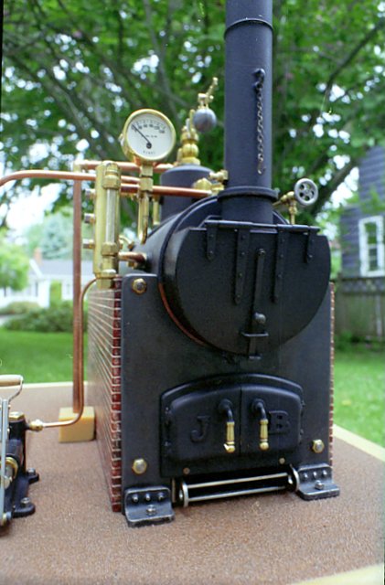
Here is a view of the boiler front
Economizer (the raised box between boiler and stack)
A PRETTY SMALL LATHE !
This little project was an early one for me. The spindle turns in ball bearings and the headstock can be swiveled to allow it to be used as a grinder. It was made from aluminum and stainless steel. It is powered by a small 6-volt motor coupled to a three-speed pulley system. The capacity is a one-inch swing and the distance between centers is about two-and-a-half inches. It is a semi-scale model of the well-known Austrian Unimat (an early blue SL MK.4).
A model builder's
It would be a great tool for building model boats. The green metal base contains nickel cadmium cells to supply electricity to the motor, making it cordless. The motor is no wimp...in its former life it powered a cordless grass string trimmer.
LARRY'S LAMP
I made this working model as a Christmas gift for our friend Larry who provided me with wise counsel and support on numerous occasions over the years. Sadly Larry passed away on December 30, 2020.
When this was written six of these guarded our city from attack by sea. As far as I know, on the only occasion we could have used them we threw up our hands and gave all our riches, and the Town Seal, to privateers. In more recent times and before the Covid 19 pandemic a procession of cruise ships came from over the horizon and during those pleasant years the flow of Gold was most happily reversed !
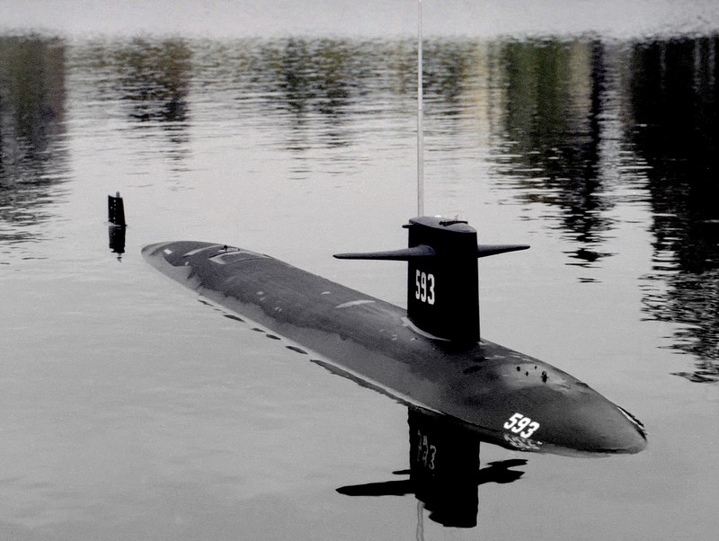
I won't forget hearing those first sketchy reports of the loss of the Thresher over WKBW radio in Buffalo.
This marine steam plant uses a twin launch engine made from castings and fitted with a Stephenson Link reverse gear.
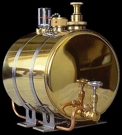
Powered by a kerosene-fired Yarrow-type boiler, it has two heated stainless steel tanks which together hold a half gallon of water.
PRESSURIZED KEROSENE TANK
For many years, Bruce Stewart & Co. produced the full size version of this 5 hp engine and a variety of smaller and larger related types. These two-stroke engines were used in the small boats of the inshore fishery on the Atlantic Coast.
ATMOSPHERIC ENGINE
HERE IS A PICTURE TAKEN TODAY (Dec. 8, 2019)
A WORKING ORNAMENT
HYDRAULIC RAM
The object above is a two-inch-high hydraulic ram or impulse pump (it is no relation to those long cylinder-piston assemblies filled with oil and now using the same name). These units can pump a small quantity of water higher than their own supply using only gravity and the momentum of the water in the supply pipe to provide the work.
A MINIATURE GASOLINE BLOWTORCH
Thanks for dropping in - and come again!
To continue on with this version of my old Engineman site use these links:
JRBentley.com


Most of the pictures presented here were taken with film before digital cameras were common and still in their infancy. The prints were scanned at 300 dots per inch. Most were 4 x 6 inch prints, processed at one-hour supermarket photofinishers. They have been in my album for years and carried all over the country. I am amazed by the quality of these images on the computer monitor - it provides near perfect lighting which is seldom found when viewing the originals.
Many of these photographs were taken with a Fujica ST-901 automatic 35mm SLR and a 24mm Pentax lens. On occasion I used a Pentax Spotmatic manual camera body. Film ranged from Kodak to K-Mart (Focal).
![]()
Birmingham Dribbler

A model mill engine steam plant with dynamo

The flywheel is 3 3/4 inches in diameter.
5/8" bore x 1 1/4" stroke


Here's an internal combustion engine that was made from a few pennies worth of leftover materials from my workshop. It's an experimental unit that I made to test my skill on several machining operations and to try out a homemade threading attachment on the Taig micro lathe.
The displacement is approximately .05 cu. in. and the base is about two inches square. The throttle return spring is actually the fuel line. It is made from silicone rubber and just pushed on with a little bit of a counterclockwise twist.....it works like a charm.
A MODEL FIRETUBE BOILER IN THE MAKING

A four-pass unit modeled after a present-day prototype - Cleaver-Brooks CBH-70
The boiler is three-inches in diameter and designed to operate at 50 P.S.I. The prototype is fired with heavy oil, but I chose to burn propane gas in the model.

Resting on a coffee mug in my workshop
during maintenance


A GRASSHOPPER ENGINE

This model was made from odds and ends and operates quite smartly at a steam pressure of only four pounds per square inch. The engine itself is about five inches long and the boiler is one and three-quarters inches in diameter. This was an early project for me, constructed before I bought my first lathe. Any turning was done in the chuck of a hand drill with a file ...not a practice that I recommend!
That's my Dad standing in the background - he passed away in 1993. He was always interested in planes, boats and engines.
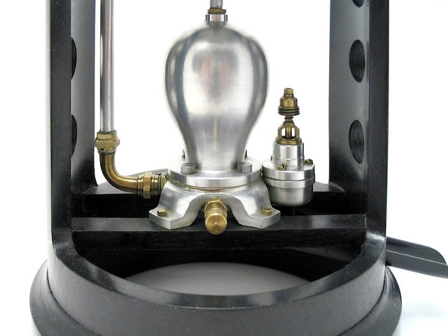
THE AEOLIPILE
The world's first rotating steam engine

A fire beneath the cauldron boils water, producing steam which is conducted through one of the copper elbows to the pivoted brass sphere. This steam issues from nozzles at the ends of the two small opposing arms on the sphere causing it to spin.
This little replica spins practically silently at 1500 RPM with a steam pressure of only 1.8 pounds per square inch.
Seated on a wooden platform to allow clearance under the five-inch flywheels, this replica has been fabricated in one-twelfth scale. No castings were used in the construction of this model. All the parts (including the flywheels) were made from flat metal sheets and bars, silver brazed together. Much of the finish work was done by hand with a file and sandpaper.
The engine was constructed from photographs, measurements and drawings which I made in the summer of 1996 from the original antique engine. Practically completed, this miniature steam engine was designed to be operated on 60 - 75 P.S.I. at 100 RPM.
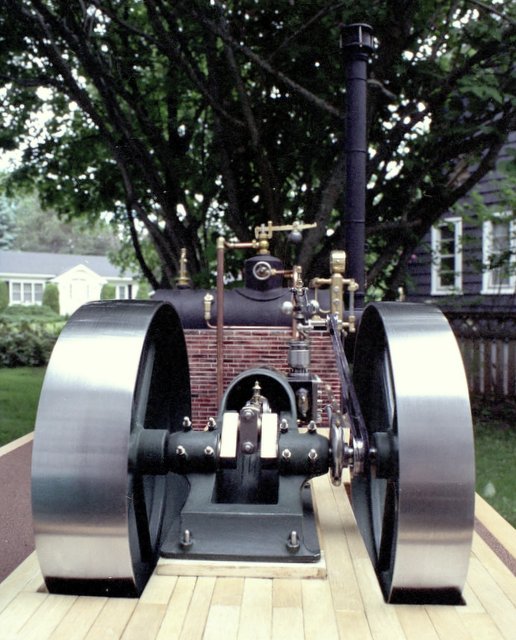
In this front view of the same engine you will notice the boiler in the background with the adjustable-weight, lever- type safety valve on top of the steam dome.
If you look closely, you can see the difference between the two pulleys: the left one has a wider rim, while the other is out farther from the crankshaft bearing to accommodate the eccentric and governor belt pulley. In practice the larger wheel was used for the main drive, and the smaller one for the auxiliaries.
Note: These shots were taken prior to much of the pipefitting that went into the final plant.
This back view shows the angled blowdown valve and spring safety valve (top at back).

This photograph was also taken before the boiler installation. The boiler shell is eight inches in length.
A STEAM POWERED HYDRAULIC ELEVATOR
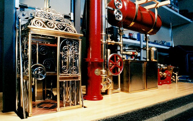
Scale: 1/24
THE ELEVATOR OF CHOICE IN 1900
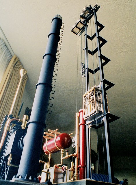
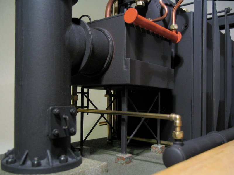
Steam for the pump is produced by an alcohol-fired boiler of the Babcock-Wilcox pattern. The boiler and water tubes are suspended by straps from an "exoskeleton-type" I-beam framework, barely visible in the background of these photographs. A 70-tube economizer extracts more heat from the boiler flue gasses before leaving via the stack.
For a sense of scale: the large vertical stack on the left of this picture is 1.5 inches diameter
The photos were taken prior to the threading of the ropes. Only a single line was attached at this point.
That is really too bad... as quadruple lines through the pulleys make quite a sight!
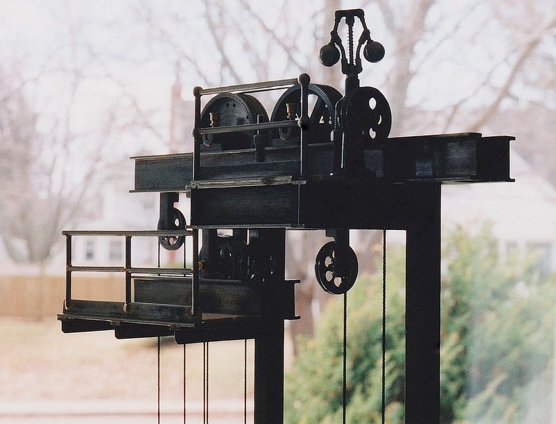

This is a large view of the top banner image on the Engineman homepage.
3-INCH SLIDING COMPOUND MITER SAW

Although this thing is tiny it can sever a wooden clothespin in half a second.
I designed it originally to use an abrasive cut-off wheel to cut the very thin brass tubing and channel stock that is sold in hobby shops everywhere. The performance really shines with a woodcutting blade installed. The cuts are extremely fast and clean. I made the table portion of this tool entirely from sheet metal - including the base and lugs. Fabrication was by silver brazing.
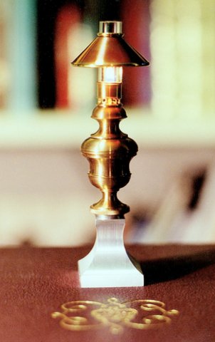
The four-inch high kerosene lamp was constructed using an old engraving in an encyclopedia. The shade is copper trimmed with brass, the body is brass and the base is aluminum. The glass chimney functions well, noticeably increasing the whiteness of the flame. It will run for a considerable time from the kerosene contained within the urn-shaped reservoir.
In the upper piture it is burning atop the 1937 Coronation Edition of the Encyclopedia Britannica in which I found a small drawing of the original outline.
During the nearly thirty years that it was in Larry's care the bright brass and copper had developed a lovely brown patina. I decided to fire it up just to see the little light burning once again.
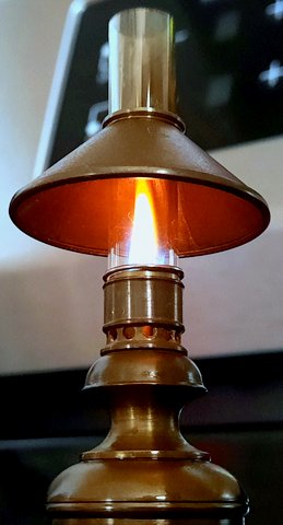
The lamp is seen in this picture below sitting on the kitchen stove
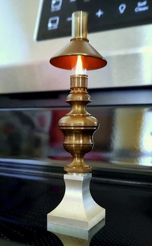
It is now five inches high with its taller chimney which was replaced after a mishap during the first year.
BOOMERS
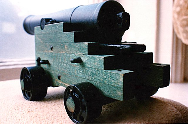
Barrel length: four inches
I made this tiny replica for my late friend Gordon who was kind enough to lend me his early Kodak digital one-megapixel camera to get some missing shots which I needed for this page.
Sadly all hands were lost on April 10, 1963.

A fifty-five-pound model of the nuclear attack submarine Thresher.
Length: 60 inches
MODEL TUGBOAT STEAM PLANT
The copper boiler has sixty-six watertubes heated by six kerosene wick lamp burners with induced draft. They are are ganged in two banks of three for easy pushrod use with future radio control. The double-walled boiler casing is entirely made of stainless steel.
In addition, there is a feedwater heater, an economizer, superheater, stack dampers, displacement lubricator, stop and throttle valves, manual and engine-driven feed pumps with filter, steam blower, whistle, exhaust steam separator, automatic regulator and safety valve, steam pressure gauge, water level gauge and a stack temperature gauge.
Bore & Stroke: 1" x 7/8" Wt: 28 lbs (wet)
THE IMPERIAL MODEL A
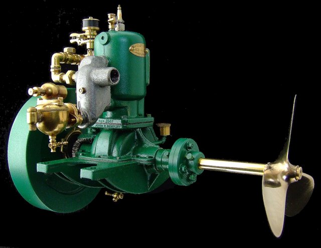
Only about the size of a baseball this is a 1/5 scale model of "The Imperial" gasoline marine motor.
In the first half of the 20th century a great number of small foundries were producing machines of this kind. Early Imperials like this one used a standard "jump-spark" ignition, later going to the more waterproof "make-and-break" system.
The little motor presented in this photo was entirely fabricated without the use of castings. This model sports a working water pump for cooling and a homemade spark plug. For purposes of display, I purchased the unfinished propeller casting from James Bliss Marine in Boston.
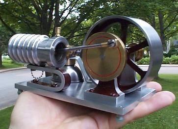
The February 1950 issue provided the plans for this little gem. It's a vacuum or atmospheric engine. It burns alcohol, makes a nice plopping sound, cost almost nothing to make and I can shut it down simply by blowing out the flame.
Well that was years ago...
Both the engine and my hand are now twenty-nine years older.
(same place but a different season!)
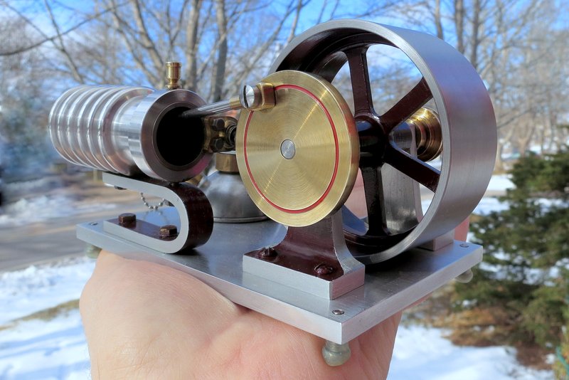
It is safe to say this engine has weathered those years very well and it still works fine.
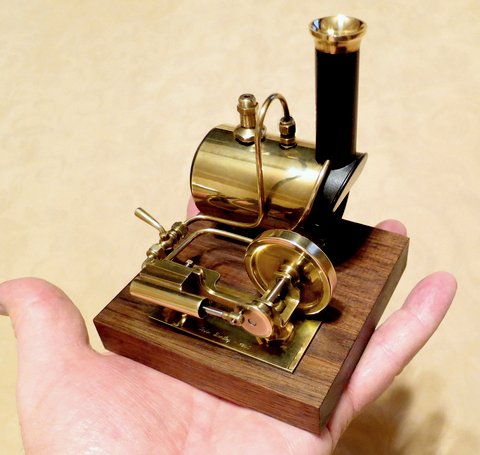
Constructed from scratch in the winter of 1995.
The entire plant is approximately three inches square and rests on a four-inch square block of American walnut.
The black PVC parts are only to display it as a working model and are nonexistent in the prototypes. The discharge pipe can be connected to either the brass nipple at the bottom front or the top of the air chamber as seen here.
overall height 3 inches

A tiny replica of a Butler 100. The tank on this torch was hollowed out from solid brass stock. It has a working air pump and vaporizing burner to produce a hot (and loud) short blue flame. I turned the handle on my Taig microlathe from the trunk of an unfortunate Flowering Crab in our back yard.
Home
Workshop
or
Go to my newer site
![]()
© John R. Bentley 2001. All rights reserved.